Introduction
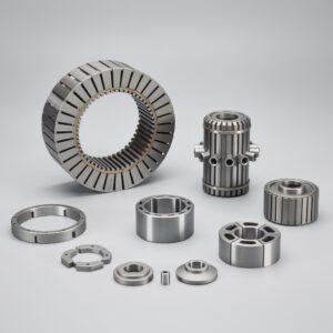
Powder metallurgy (PM) is a very large family of processes, including Press and Sinter (P&S), Metal Injection Molding (MIM), and Spark Plasma Sintering or Field Assisted Sintering Technique (FAST/SPS), along with dozens if not hundreds of others. Each process follows different physics, imposes different design constraints, and serves different applications.
Exhibit 1: Every powder metallurgy process starts with metal powder.
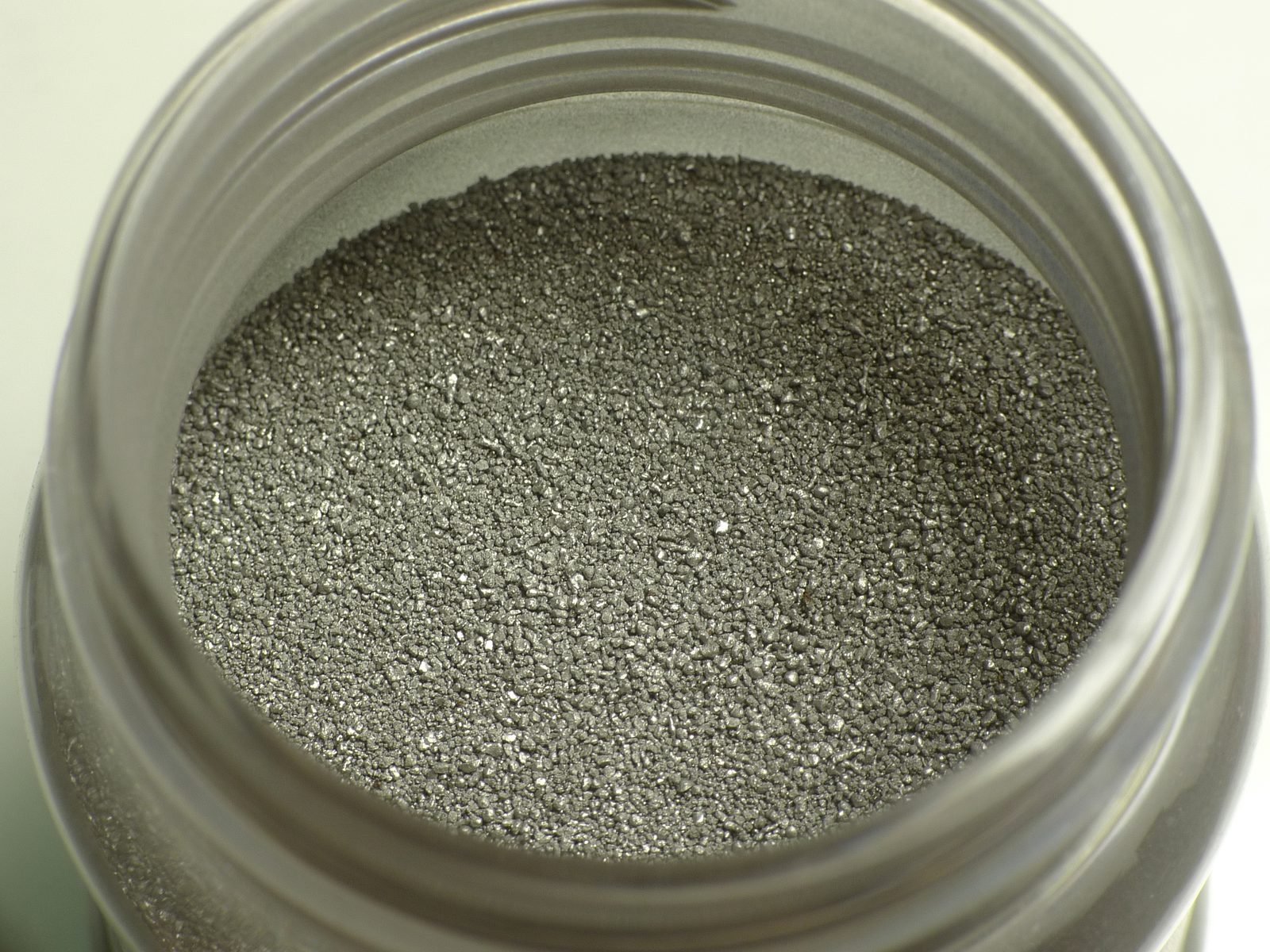
What happens next (pressing, molding, or field-assisted sintering) determines the characteristics of the finished part.
Most engineers approach us by asking, “Can powder metallurgy make this part?” But that is the wrong first question. A better one is: “Which powder metallurgy process best fits this component, given its purpose, material, geometry, and production requirements?”
Once we know the specifics of your part and any challenges you’re facing, we can proceed with a Design for Manufacturing (DFM) analysis, before tooling or supplier quoting begins. Through DFM, we can determine whether powder metal is right for your part and select the right PM process. We don’t just tool up a part and manufacture it, we bring our knowledge of powder metal, our experience, and most importantly our creativity to see if there is a way to make your part faster, stronger, or less expensive.
The Importance of DFM and Process Selection in Powder Metallurgy
Powder metallurgy DFM means adapting the part design to the way powder flows, fills the cavity, compacts, sinters, shrinks, densifies, and finishes. A drawing ideal for machining may be expensive, fragile, or unrealistic in powder metallurgy unless geometry, tolerances, material, and process route are reviewed early. This process should occur up front; the later you discover any issues, the more it costs to fix them.
Exhibit 2: A CAD model and the aluminum part machined from it.
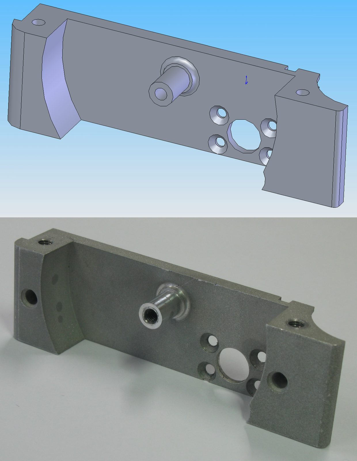
Geometry that is straightforward to mill is not automatically suited to a powder metallurgy process. Processes such as P&S, MIM, and SPS do not necessarily offer a technically sound or commercially competitive solution. Before the design is frozen, run the part by a powder metal application consultant who can provide timely feedback on technical feasibility and pricing.
DFM in powder metallurgy starts with process selection and application. Only after the right process is confirmed does it make sense to optimize geometry, tolerances, wall thickness, and secondary operations. Selecting the wrong process can make a good design technically and commercially unworkable. If a part scores well on geometry for Press and Sinter, but requires 98% density for fatigue resistance, MIM may be the way to go. A material that cannot be sintered conventionally (vacuum/belt) may require FAST/SPS regardless of geometry.
A process selection review at the concept stage costs a conversation, while a process change after the release of tooling costs significantly more.
Why Considering Powder Metal Early in the DFM Process Is Critical
Here’s an example of how Powder Metal Technologies was able to generate cost savings for a client in the automotive industry by being involved in the process early. The design engineers sent us the CAD models for two parts they wanted to make, to be used in an electric vehicle contactor. We put the parts through the DFM process for both P&S and MIM and submitted new geometries for evaluation. A back-and-forth conversation with the customer, the P&S company, and the MIM company took place over six months where we discussed part designs, materials, and prices for different versions of the parts. In the end, we decided on two MIM parts with unique geometries that cannot be made with any other process and can be produced very affordably.
We then worked for the next year and a half with the customer to identify the right tooling configurations, materials, and gate location (a very important decision that helps determine how well the part molds) and to prototype and test the parts to determine the tolerances we could hold. In the end we proved that MIM could be used to create parts with virtually the same magnetic properties as a machined version, but could be produced at volume for 10% to 20% the cost per part.
By getting us involved at the beginning of the project, the customer and design engineer ended up with a very elegant technical and commercial solution. Read more about PM/MIM magnetic materials for electrification in our case studies.
What This Guide Covers
In this guide, we’ll focus on process selection, comparing three of the leading production-capable powder metal processes: P&S, MIM, and FAST/SPS. The goal is to give you the foundation you need to have a productive discussion about your goals and determine the PM process that will help you get there.
The right decision will allow you to optimally design and manufacture your part, saving you the expense and headaches of learning your lessons the hard way. This guide is part of the Powder Metal Technologies Knowledge Center.
How Engineers Choose Between P&S, MIM, and SPS
Certain production techniques, geometries, functions, or materials will suggest whether P&S, MIM, or FAST/SPS, or another process, should be the starting point for an engineering evaluation.
Following is a quick introduction to the three processes.
Press and Sinter: Best Process for High-Volume Structural Parts
Press and Sinter is often the first process to evaluate when a part has pressable geometry, moderate complexity, and annual volume high enough to justify tooling. P&S offers low material waste and competitive cost per part at volume. A mature supplier base is in place for iron, steel, stainless steel, copper, and bronze alloys. A good reference for more information on Press and Sinter is the Metal Powder Industries Federation (MPIF), which publishes material and design standards providing guidance on what P&S can typically achieve across density classes and tolerance grades.
Exhibit 3: Press and sinter shapes
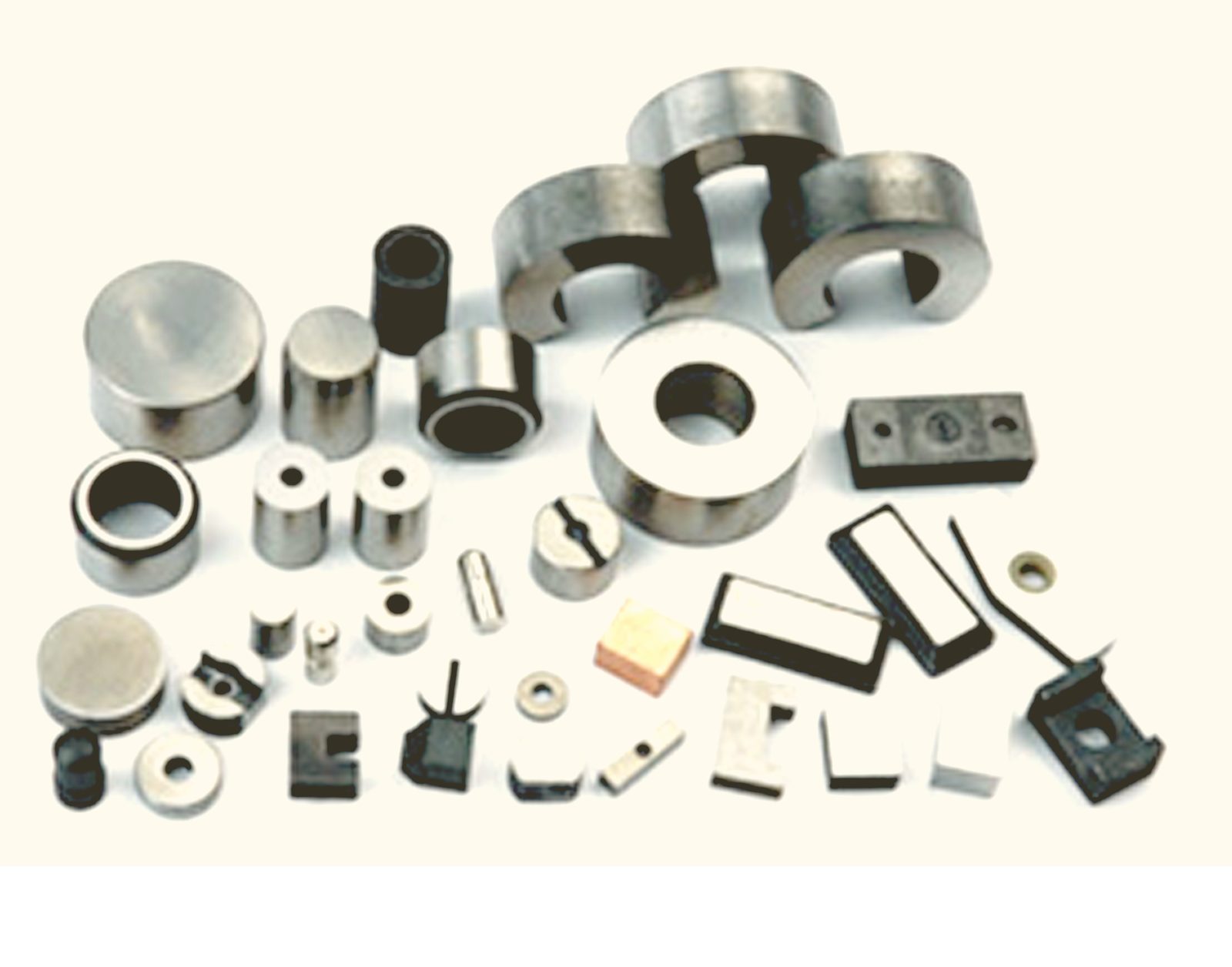
Image: Joan.ortega, CC BY-SA 3.0, via Wikimedia Commons
MIM: Best Process for Small, Complex Metal Parts
MIM is commonly the preferred route when the part is small, is complex in three dimensions, requires high density, and would be uneconomical or impossible to produce by P&S, machining, or casting at the required volume. The Metal Injection Molding Association (MIMA) publishes material standards and design guidance engineers can refer to during process evaluation.
FAST/SPS: Best Process for Advanced Materials or Ceramics
FAST/SPS is generally the right starting point when the material, microstructure, bonding/joining requirements, or densification is the primary engineering problem, rather than high-volume production economics. This process is commonly used for technical ceramics, hard materials, high-entropy alloys, functionally graded materials, and dissimilar-material bonding. These are all areas where conventional sintering equipment may not achieve the required density or microstructure.
Determining Which PM Process Is Right For Your Part
Exhibit 4 lists some of the typical characteristics you might be trying to solve for in your part, and the process they suggest. These guidelines do not determine the final answer; rather, they are a starting point for a more detailed review with a consultant, process-knowledgeable supplier, or engineering representative. These experts will look at geometry, material, volume, and supplier capability to make the final decision on process suitability.
Exhibit 4: Initial Considerations for Process Selection: P&S vs. MIM vs. SPS.
| If the component requires… | First process to evaluate |
|---|---|
| High-volume structural production | Press and Sinter |
| Simple or moderately complex axial geometry | Press and Sinter |
| Magnetic function (permanent or soft magnetic) | Press and Sinter (or legacy magnet PM processes) |
| Thin walls, fine features, or part consolidation | MIM |
| Advanced materials, ceramics, bonding, or microstructure control | SPS/FAST |
Exhibit 5: Process-selection review.
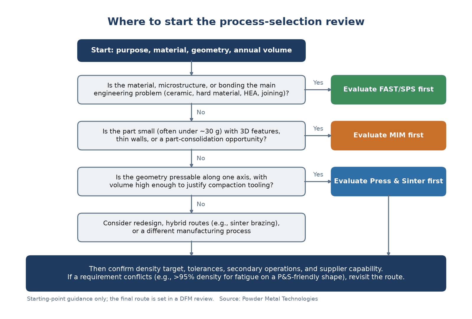
Three questions point to the first process to evaluate: FAST/SPS when the material, microstructure, or bonding is the main engineering problem; MIM for small, complex 3D parts; Press and Sinter for pressable axial geometry at volume. Whichever route the chart suggests, confirm density, tolerances, secondary operations, and supplier capability in a DFM review before committing. Review with a powder metallurgy application consultant for professional guidance during the process.
Source: Powder Metal Technologies
Exhibit 6: Summary of the best-fit applications and watch-outs engineers should evaluate before committing to a decision about whether P&S, MIM, or FAST/SPS is right for a particular component.
| Process | Best Fit | Watch-Outs |
|---|---|---|
| Press and Sinter (P&S) | High-volume structural parts: gears, sprockets, bushings, cams, levers, pulleys, and mechanical components | Limited 3D complexity, density gradients, pressing direction constraints, ejection requirements, tooling cost at low volume |
| Metal Injection Molding (MIM) | Small, complex, high-density metal parts with thin walls, fine features, and 3D geometry | Higher feedstock cost, shrinkage control (10%–20%), debinding cycle, mold design complexity, volume requirements to justify tooling |
| Spark Plasma Sintering (FAST/SPS) | Engineered materials, technical ceramics, hard materials, specialty alloys, bonding, and advanced material development | Equipment-dependent size limits, batch economics, graphite tooling common but not universal, material qualification requirements |
Source: Powder Metal Technologies
Often engineers select Press and Sinter by default because it is the most familiar powder metallurgy process. This is a mistake. Each PM process has specific uses and the determination of which is best depends on the specifics of your part. Selecting P&S without a thorough review often leads to a mid-program discovery that the density requirement, geometry complexity, or material system demands a different route — leading to delays and added costs.
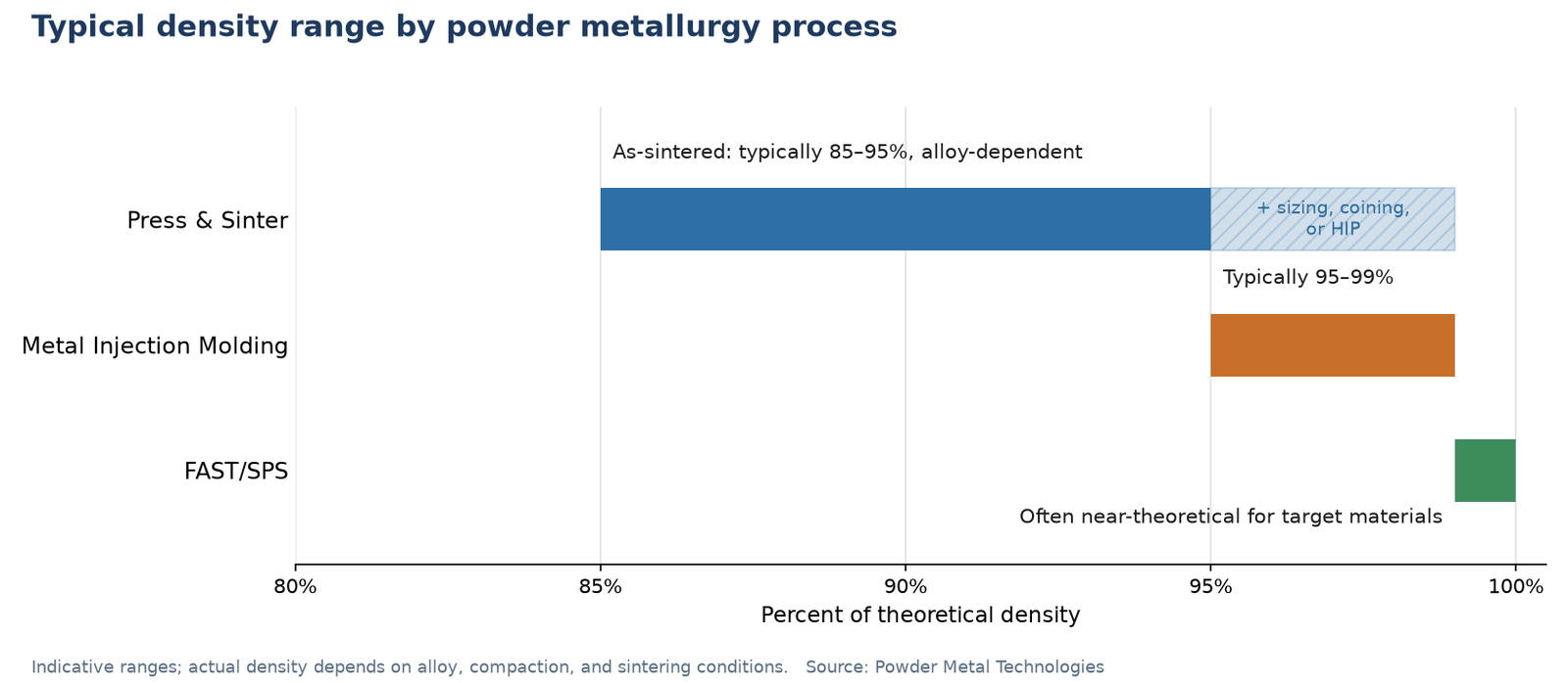
Exhibit 7: Typical density range by powder metallurgy process.
Source: Powder Metal Technologies
Press and Sinter Design Guidelines
Press and Sinter should never be the default choice, but it is the most widely used powder metallurgy process for structural metal components. The process fills a die cavity with metal powder, compacts it under high pressure to form a green compact, which holds its shape but is fragile, then sinters it in a controlled-atmosphere belt furnace, adding strength.
Exhibit 8: A powder compaction press.
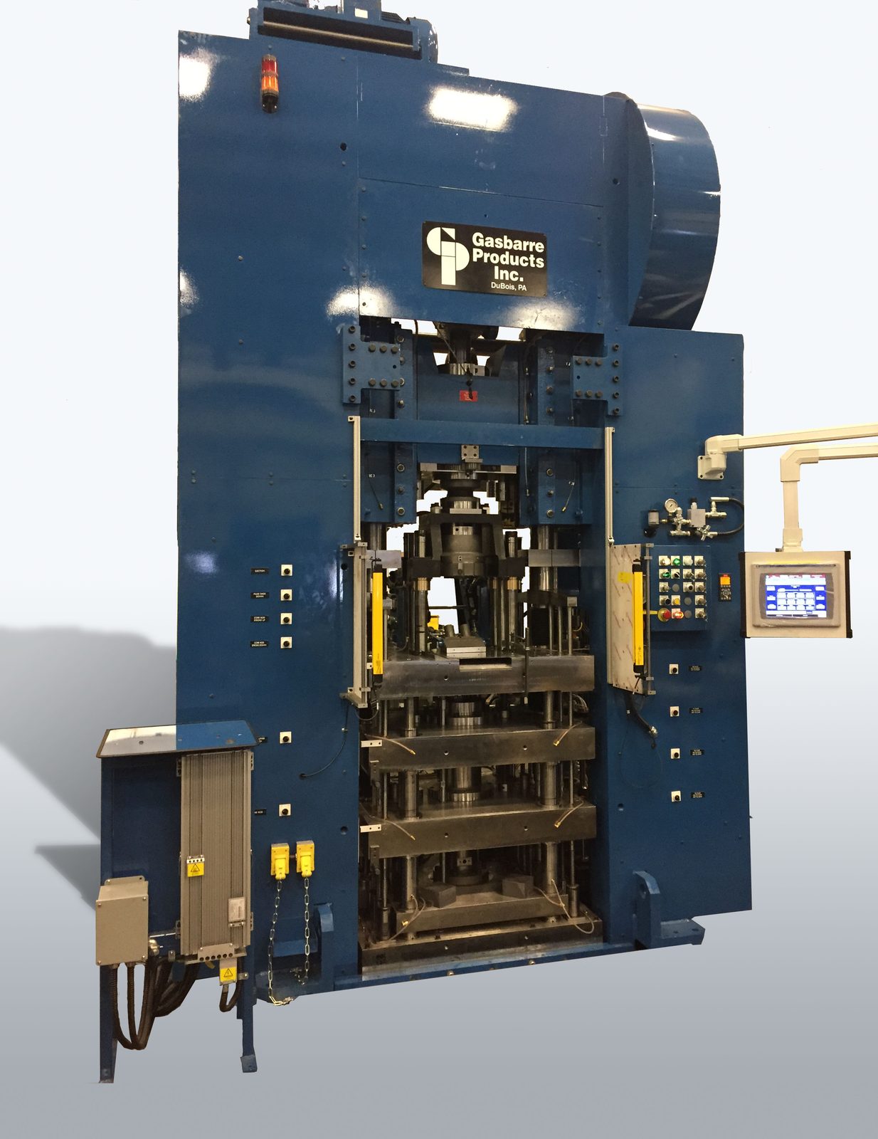
Metal powder is pressed in a rigid die between upper and lower punches to form a “green” compact, which is then sintered in a controlled-atmosphere belt furnace.
As-sintered density typically falls in the range of 85% to 95% of theoretical density, though the achievable range depends on the alloy, compaction pressure, and sintering conditions. P&S net shape parts — final parts out of the furnace — are typically 10%–12% porous, but can be infiltrated if needed to seal porosity. Secondary operations such as sizing, coining, or hot isostatic pressing (HIP) can increase density and control feature size when required. All of this means that Press and Sinter parts are legitimate metal parts that are used in highly aggressive applications.
In the next figure, you can find four circular micro-sections, labeled A to D, showing that powder particles pack more tightly as compaction increases, with magnified details below.
Exhibit 9: Cross-sections of a powder compact at increasing compaction (A to D).
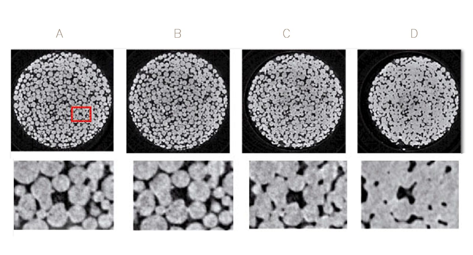
As pressure rises, particles deform and pores are either eliminated or decrease in size. Some porosity remains (approx. 10%), which is why P&S density is specified either as a minimum or a range rather than a specific target density value.
Press and Sinter Design Rules
Once you’ve selected P&S as your process and understand its pros and cons, the next step is to design the part with its characteristics in mind. The MPIF’s Powder Metallurgy Standards provide density class definitions and typical material property ranges engineers can use to set realistic targets for the following design factors.
Design around the pressing direction. P&S tool design is a unique, hard-to-find skill set that is completely different than all other types of tool design, with a unique set of tools and guidelines. In P&S, compaction and ejection occur along a vertical axis, and that is how the part should be designed. Undercuts, transverse holes, and re-entrant shapes must be redesigned or added through secondary machining.
Exhibit 10: A sectioned P&S compaction tool (left, shown on its side) with the part it produces (compacts) on the right.
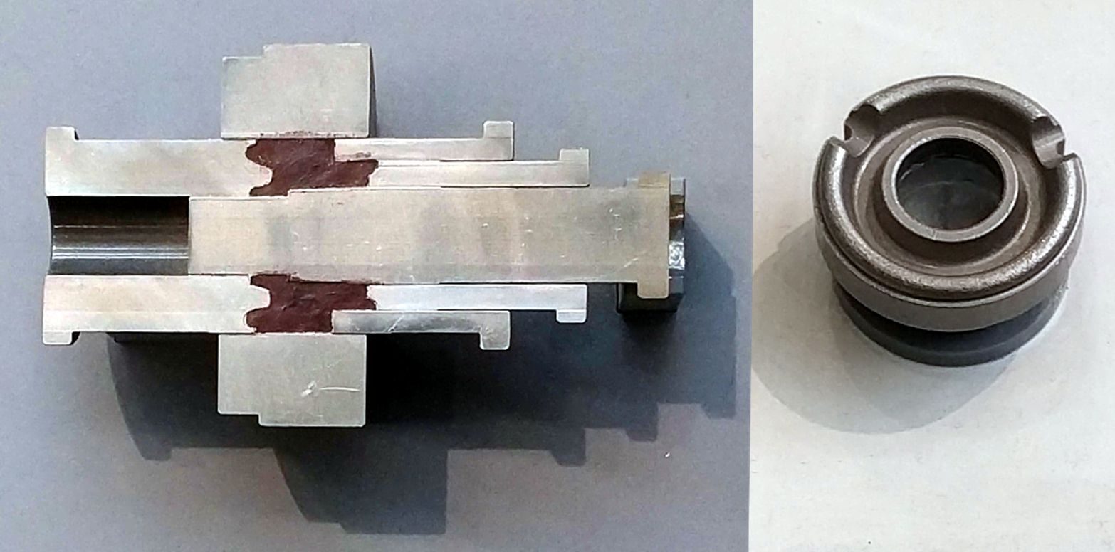
Note that the concentric punches, core rod, and die all move along one axis located in the “center” of the nested tooling members. Every geometric part feature must be compressed along the axis (vertical in press operation) and subsequently ejected from the die. Part features that can’t be compressed (ejected) along the axis either need to be modified during the DFM phase or require a secondary machining operation post-press and sinter.
Keep wall thickness uniform. This is a unique characteristic of P&S. Abrupt cross-sectional changes create density gradients that can cause distortion or cracking during sintering. Practical minimum wall thickness depends on part size, alloy, and tooling design. It is essential to consult the supplier or a skilled P&S tooling designer during early DFM review rather than applying a universal threshold.
Specify functional tolerances only. P&S has unique dimensional and tolerance requirements. While MPIF design standards provide typical tolerance grades by density class, as-sintered dimensional tolerances for P&S are supplier-and geometry-dependent. Applying machining-level tolerances to every feature eliminates the cost advantage of the process.
Plan secondary operations before tooling is released. A complete P&S manufacturing plan will typically include secondary operations such as threads, cross-holes, bearing surfaces, and case hardening. Make sure you account for these upfront rather than discovering them after tooling is cut, and remember that secondary operations will add cost to the part.
Specify a density class rather than a single density value. Press and sinter requires a density range because of the intrinsic variability in the process. Specifying a density class using MPIF Standard 35 material and mechanical property data gives the supplier flexibility to optimize its process for the functional requirement of your part.
Exhibit 11: Considerations in Press and Sinter Design.
| Design factor | Good P&S design | Risky P&S design |
|---|---|---|
| Pressing direction | Features aligned with compaction axis | Cross-features, undercuts, transverse holes |
| Wall thickness | Uniform sections; minimum wall thickness varies by part size, alloy, and tooling, but thin sections increase density gradient risk | Abrupt thick-to-thin transitions; very thin walls without process review |
| Corners | Chamfers at 30°–45° with .010” flat; internal radii where needed | Sharp internal corners |
| Tolerances | Functional tolerances on critical features only | Machining-level tolerances applied universally |
| Density | Realistic target for the process | Full theoretical density assumed without secondary ops |
| Secondary operations | Planned before tooling release | Discovered after first article inspection |
| Length-to-wall ratio | Below 8:1 | Above 8:1 creates unavoidable density gradients |
Source: Powder Metal Technologies
A Creative and Cost-Effective Press and Sinter Solution
PMT assisted in a situation recently where P&S was able to solve multiple problems for a client who came to us early in the design phase. The customer had an assembly of two parts that worked together within an automotive disconnect. The engineers were initially thinking of machining the parts. But the geometry of the parts was very, very expensive to machine. The client came to us at the front end to see if powder metal might be a solution.
With a 3- to 4-inch diameter, the parts were too big to consider MIM. So we started by prototyping, tooling, and testing different design concepts to determine the pros and cons of using P&S to manufacture the part. For the first part, we ended up with a very creative solution suggested by our trusted P&S partner. The idea was to buy a simple, 50-cent machined ring and affix a powder metal addition to it, bonding them together in a sintering furnace (sinter brazing). The result was much more affordable than the machined version and meets all the technical criteria for the application.
The second part was designed using the same unique and very strong material that was used for the powder metal component in the specially designed first part, allowing the two parts to interface and function effectively in the product. The assembly consisting of the two parts is now in production, with 5,000 pieces a week being made.
We could not have produced an assembly with this geometry affordably without powder metal. And we would never have been able to settle on a creative solution such as this without being involved in the DFM process early. For another example, see how press and sinter chromium steel replaced machined 4140 steel at over 50% cost savings.
Metal Injection Molding Design Guidelines
Unlike Press and Sinter, where parts go through a belt furnace, MIM uses a vacuum furnace. As a result, MIM combines the geometric freedom of plastic injection molding with the material properties of a vacuum-sintered metal part, such as higher density.
The process uses a feedstock of fine metal powder mixed with a thermoplastic or wax-based binder. The feedstock is injection-molded into a cavity; the binder is then removed through a debinding step (solvent, aqueous, catalytic, or thermal, depending on the binder system), and the resulting fragile “green part” is vacuum sintered to high density.
Exhibit 12: The MIM process.
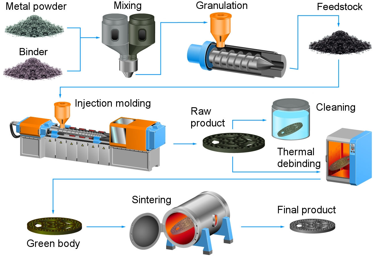
Image: Carloburkhardt, CC BY-SA 4.0, via Wikimedia Commons
MIM typically achieves 95% to 99% of theoretical density for common alloys, supporting mechanical properties that can approach wrought or machined equivalents, although property comparability is alloy- and application-dependent.
Exhibit 13: How MIM reaches high density.
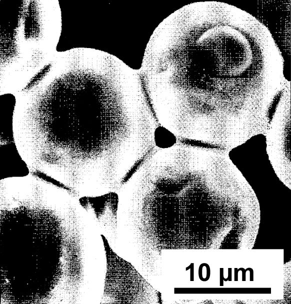
Image: CarloBurkhardtHSPF, CC BY-SA 4.0, via Wikimedia Commons
When MIM is the Right Choice
MIM is a strong fit when the component is small (often below roughly 30 grams, though this is not a hard threshold), has 3D geometric complexity that would make machining prohibitively expensive at volume; requires high density, such as for gas sealing or to lengthen a part’s life before fatigue sets in; or offers an opportunity for part consolidation that eliminates assembly operations.
Exhibit 14: Eyewear hinge components made by metal injection molding (MIM).
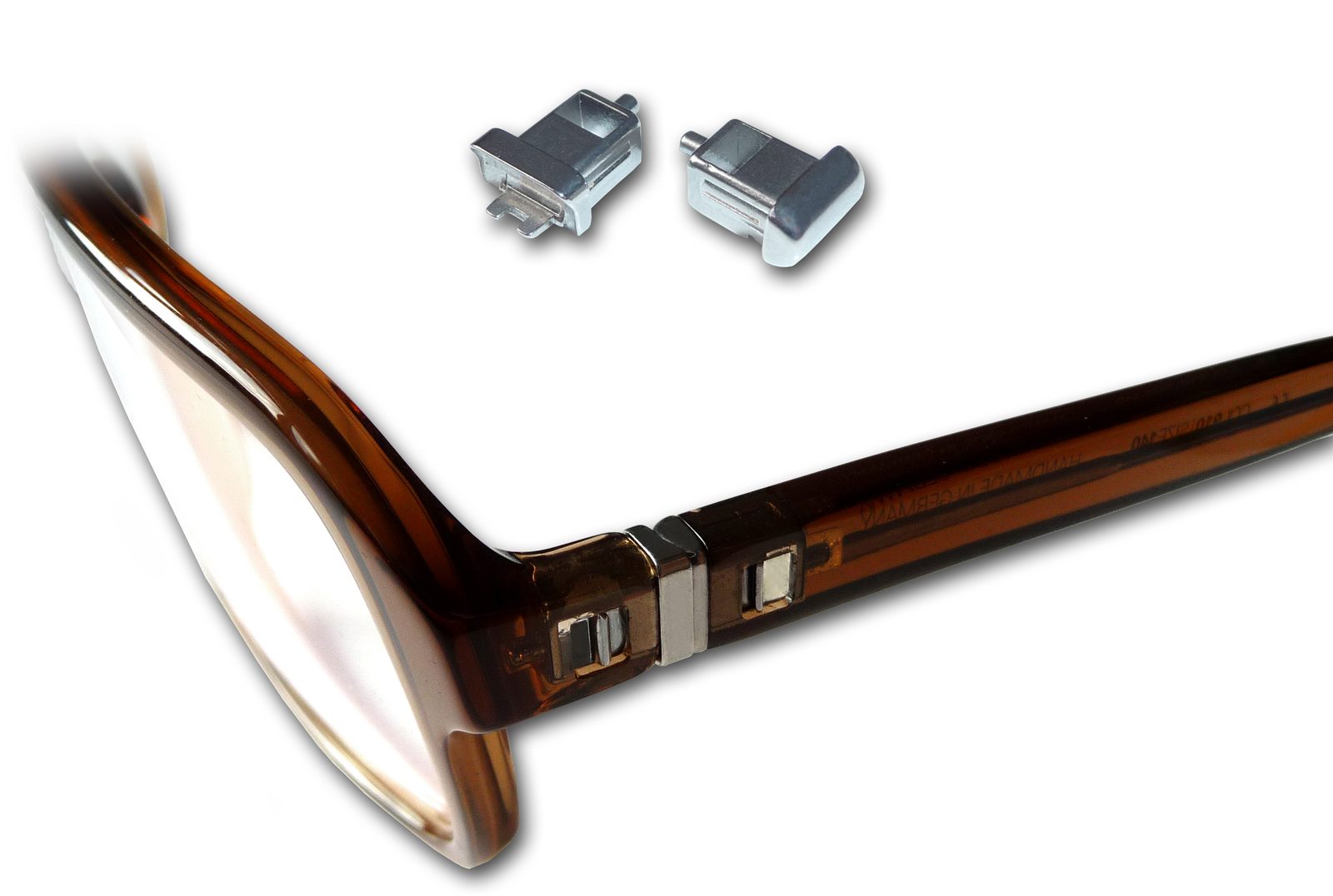
Image: Carloburkhardt, CC BY-SA 4.0, via Wikimedia Commons
MIM works well when a component is difficult to manufacture economically with Press and Sinter, machining, or casting. Production economics are typically most favorable at higher annual volumes; millions of pieces per year is ideal but the specific threshold depends on part complexity, tooling cost, and material.
Exhibit 15 compares MIM and Press and Sinter along various design factors.
Exhibit 15: MIM vs. Press and Sinter: A Comparison of Design Rules.
| Factor | Favor P&S | Favor MIM |
|---|---|---|
| Part geometry | Axial, moderate complexity | 3D, high complexity |
| Part size | Approx. 5 pounds max. | Typically under 30 grams |
| Density requirement | 85%–95% (10% porous net) | 95%–99%+ (near zero porosity-capable) |
| Production volume | 10,000 to 1M+ per year | Min. 100,000, ideally millions |
| Material system | Standard PM alloys, soft magnetic composites (SMCs) | Stainless, titanium, superalloys |
| Cost driver | Limit process steps | Fine metal powder |
Source: Powder Metal Technologies
MIM Design Rules
Following are some considerations to keep in mind when designing parts for MIM.
Design for uniform wall thickness. Uneven cross-sections create differential shrinkage during debinding and sintering, causing warping or dimensional variation. Where thick sections are unavoidable, use coring or ribs to remove material and save money.
Account for sintering shrinkage in the tool. From molding to finished components, a part shrinks about 20%, depending on material and feedstock formulation. Shrinkage is generally predictable for a qualified material-process combination, but the mold must be designed with shrinkage compensation built in from the start. Often a prototype tool is recommended to dial in the shrink percentage (especially on critical features) before a production tool is ordered.
Exhibit 16: A typical MIM thermal cycle.
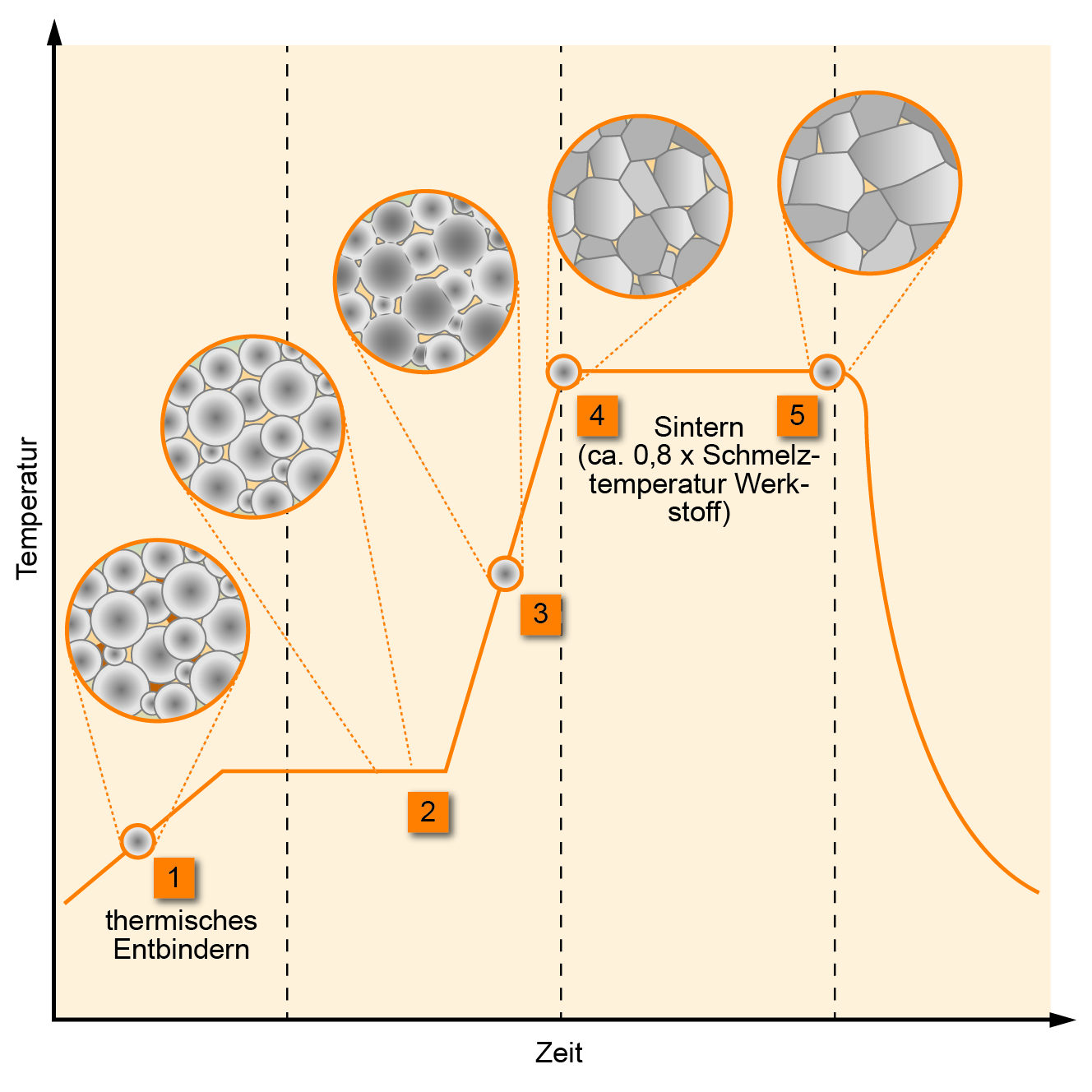
Residual binder is removed at low temperature, then the part is heated to roughly 0.8 × the alloy’s melting temperature. There, the particles bond, grains grow, and the part shrinks 10% to 20% from the green state after molding to its final “as sintered” size.
Image: CarloBurkhardtHSPF, CC BY-SA 4.0, via Wikimedia Commons
Use part consolidation strategically. MIM can combine individual parts or assembled features into a single molded part, reducing assembly labor and simplifying tolerances.
Exhibit 17: Part consolidation with MIM.
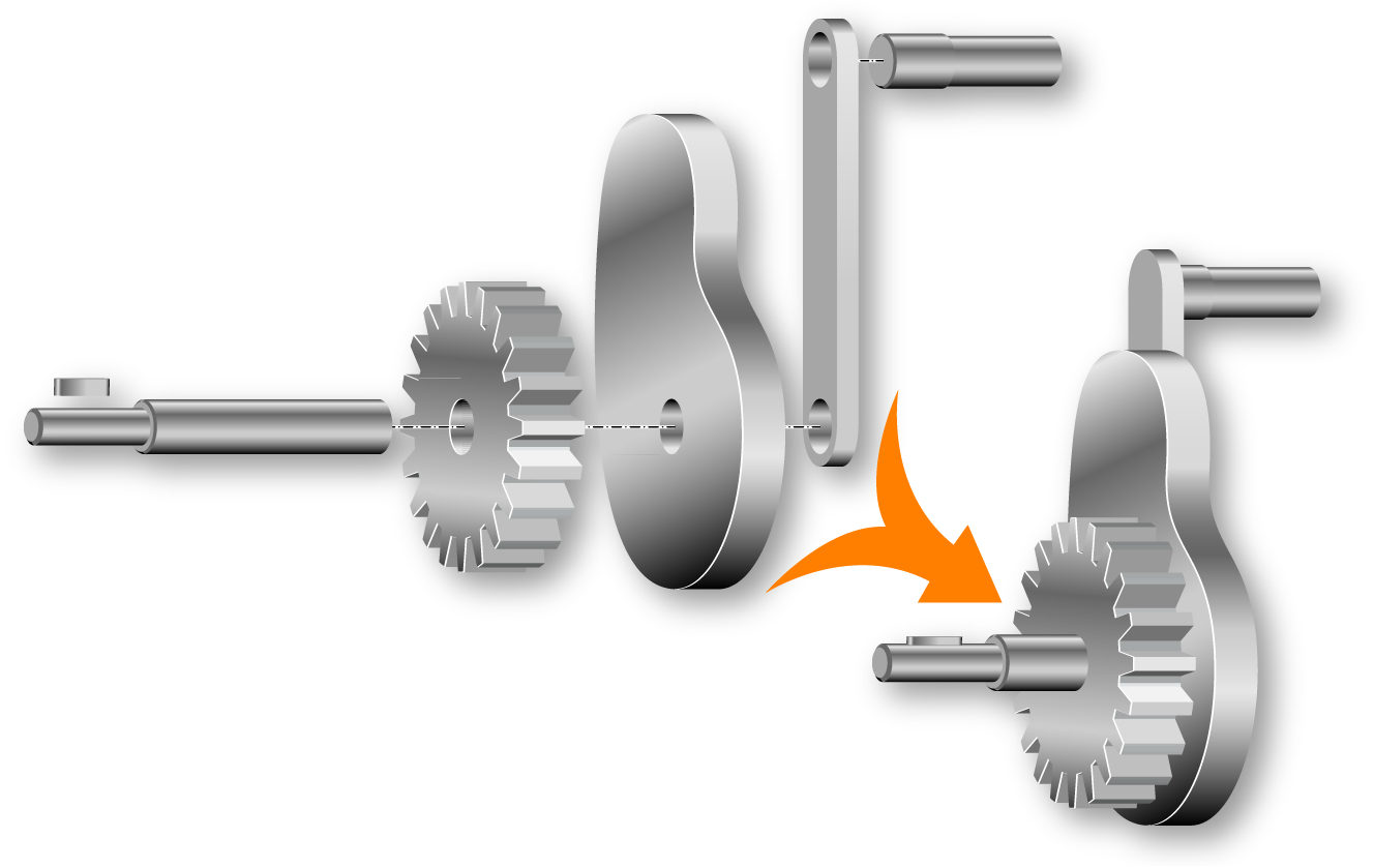
Image: Carloburkhardt, CC BY-SA 4.0, via Wikimedia Commons
Review thin walls and fine features early. MIM can produce relatively thin walls, but achievable minimums are material- and geometry-dependent. Features that are very thin require careful review of feedstock flow, green strength, staging, sintering process, expert tool design, and precision tooling manufacturer.
Select the right material. MIM is well established for stainless steels and low-alloy steels. Titanium alloys, nickel superalloys, and cobalt-chrome are also processed by MIM but are more specialized applications with additional process and qualification considerations. ASM International publishes material data for MIM alloys engineers can use for property comparisons.
Generating Cost Savings Through an Innovative MIM Solution
A customer sent us a part it had in production, wanting to reduce the cost. It was an aluminum screw-machined part, which would typically not use powder metal. However, it was a small part with a lot of geometric features, produced in a high volume of 5 million pieces a year — perfect for MIM.
The client and our MIM vendor thought that MIM would not be able to compete on cost with the aluminum screw-machined version, but the MIM vendor loved the design and wanted to quote a version of it made from stainless steel. In the end, the process yielded the desired cost savings. The part could be manufactured much faster, taking 10 seconds to mold four units with MIM, versus 30 seconds to machine one on a screw machine, due to the complex geometry. In addition, the part was more resistant to corrosion, since stainless steel was being used instead of traditional aluminum.
Rather than just doing it the traditional way, as would be typical for a part like this, the client was able to generate significant cost savings — and other benefits — by bringing it to us early and giving us the opportunity to think outside the box and suggest this innovative MIM solution. A similar technology transfer from machining to MIM is described in our case studies.
A Third Option: FAST/SPS
Spark Plasma Sintering, also referred to as Field-Assisted Sintering Technology (FAST/SPS), is a pressure-assisted powder consolidation process that uses pulsed electrical current and applied pressure to rapidly densify powders or bond dissimilar materials via Joule heating.
Exhibit 18: Layout of a FAST/SPS system.
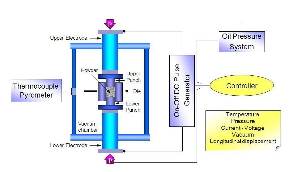
Image: Yalda Tarpoudi, CC BY-SA 4.0, via Wikimedia Commons
FAST/SPS is generally not suited to commodity high-volume structural production, except in cases where a higher cost can be absorbed (e.g., in the medical, aerospace, defense, or nuclear industries). It is an advanced materials processing tool used across research, development, and specialty manufacturing.
Rapid heating rates, simultaneous pressure application, and short cycle times allow FAST/SPS to densify materials in a way that is difficult or impractical to achieve with conventional sintering or brazing. The process can also help retain small grain size, which makes a part stronger, and join both dissimilar and similar materials.
Exhibit 19: View through the viewport of a spark plasma sintering chamber.
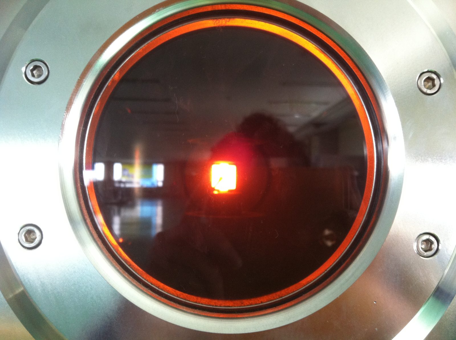
Image: Raihan.Rumman, CC BY-SA 3.0, via Wikimedia Commons
When Should Engineers Use FAST/SPS Instead of Press and Sinter?
Engineers should consider FAST/SPS when material performance, grain size, ceramic processing, hard materials, or dissimilar-material bonding are the primary engineering challenges rather than high-volume production economics.
FAST/SPS becomes a good alternative when:
-
- The material would not reach acceptable density through conventional belt or vacuum sintering
-
- A highly engineered application requires a fine-grained microstructure and would coarsen at conventional sintering temperatures
-
- The component is a technical ceramic, hard material, or functionally graded material
-
- The part incorporates dissimilar materials that need to be joined without a brazing filler or adhesive
When Should Engineers Use FAST/SPS Instead of MIM?
FAST/SPS may be a better fit than MIM when the application involves advanced materials, technical ceramics, hard materials, or lower-volume specialty components where MIM tooling and feedstock economics are not justified. MIM may not be technically feasible for materials that are difficult to debind; FAST/SPS often doesn’t require a material binder, which avoids the debinding process and gives you more control. FAST/SPS also may be a better option for materials that are highly reactive or require very high sintering temperatures.
What Materials Are Best Suited for SPS/FAST?
Materials often dictate the use of SPS/FAST, including:
-
- Technical ceramics: alumina, zirconia, silicon carbide, silicon nitride, boron carbide
-
- Hard materials: tungsten carbide, cemented carbides, boride-based hard materials
-
- High-entropy alloys (HEAs): five-element alloys that require controlled processing
-
- Functionally graded materials (FGMs): gradient compositions transitioning between materials within a single part
-
- Thermal management materials: diamond-metal composites, copper-molybdenum
-
- Refractory metals: tungsten, molybdenum, rhenium
-
- Dissimilar material combinations: metal-ceramic joints, graded interfaces, bonded layered structures
Exhibit 20: Silicon nitride bearing balls from 1 mm to 20 mm.
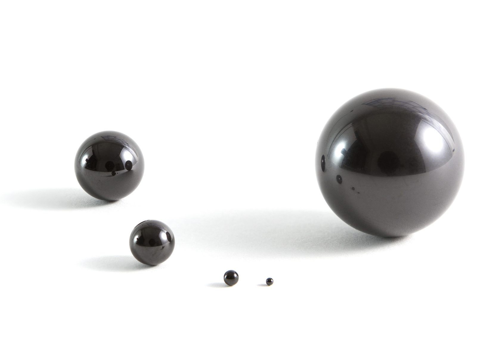
Image: Lucasbosch, CC BY-SA 3.0, via Wikimedia Commons
What Are the Design Limitations of FAST/SPS?
Engineers should be aware of the limitations of FAST/SPS.
-
- Size: Maximum part size depends on equipment; many systems are limited to smaller tooling diameters, though larger-scale systems (400 mm) exist
-
- Batch economics: In the past, FAST/SPS typically processed one or a small number of parts per run, although recent advances in press equipment allow for high-volume production for high-value applications
-
- Graphite tooling: Graphite is the most common die material and limits geometry options; it can also introduce carbon contamination in reactive materials. Alternative tooling materials are used in specific applications
-
- Qualification: Regulated applications in aerospace, medical, and defense require extensive process documentation and testing
Exhibit 21: How does FAST/SPS compare with P&S and MIM?
| Selection factor | Press and Sinter | MIM | FAST/SPS |
|---|---|---|---|
| Best use case | High-volume structural components | Small, complex, high-density parts | Engineered materials, ceramics, bonding |
| Geometry complexity | Moderate | High | Low, application-dependent |
| Density potential | Typically 85%–95% (alloy-dependent) | Typically 95%–99% | Very high; often near-theoretical for target materials |
| Volume fit | Medium to very high | Higher annual volumes | Typically lower volume, specialty applications. New SPS press technology can produce high yearly quantities for high-value applications |
| Material flexibility | Strong for structural alloys | Strong for fine metal powders/most alloy systems | Very strong for advanced and difficult-to-sinter materials, highly engineered material systems |
| Tooling economics | Production tooling driven | Mold and shrinkage driven | Graphite tooling common; batch-process driven |
| Typical decision driver | Cost per part at volume | Complexity and density | Material performance or joining challenge |
Source: Powder Metal Technologies
SPS Solves a Bonding Problem in a Revolutionary Way
Soft magnetic composite materials (SMCs) are used to produce axial flux motors, which are smaller, lighter motors with more power and torque than regular radial flux electric motors. Parts made with SMCs — essentially iron particles coated with a composite — are heat treated and have unique magnetic properties. They are not usually manufactured using Press and Sinter because they do not have the simple axial pressed shapes that P&S requires. To make complex shapes with P&S, two to three different parts are made and then glued together with an adhesive.
A customer told us they were manufacturing separate SMC parts, from which they were creating a big tower. But the adhesive used to glue the parts together wasn’t strong enough and the towers were breaking apart. We had the idea to try to bond the parts using SPS. The customer placed an R&D order with one of our partner companies and, sure enough, we were able to mechanically bond the parts in our SPS presses. Bonding with pressure and heat gave a strong bond compared to the adhesive, and on top of that we saw an increase in the magnetic properties.
This is another example where a consultant like PMT can bring its knowledge and experience to the table and create a wholly new way to solve a problem. In this case, this new process could revolutionize what can be done with SMCs, including bonding them to copper or aluminum substrates. We have seen lots of interest in this new process from makers of axial flux motors. Related reading: reducing neodymium magnet size by one-third for an electrification application.
Working With a Powder Metallurgy Consultant
It is important to select the right PM process, as the first step in a full DFM review, before the design is frozen and suppliers are selected. An engineer who has committed to a specific PM process, material, and tolerance stack before engaging a PM specialist has fewer options and higher change costs.
In addition to process selection, a DFM review typically covers a geometry review against process constraints, the selection of materials and an availability review, a tolerance analysis, a supplier capability assessment, and qualification planning for regulated applications.
Retaining the services of a powder metallurgy consultant or engineering representative smoothes the DFM process. These professionals know which geometries cause tooling problems, which density targets require a process change, which materials are available from qualified suppliers, and which tolerance requirements will need secondary operations the original design did not account for.
More importantly, our expertise, deep knowledge of powder metal materials and processes, and strong relationships with trusted vendors for each PM process allows us to bring creative solutions to the table. We can solve problems, both technical and commercial, in new ways that not only address the specific issues you face but also bring additional advantages beyond what you expect.
For OEM engineers evaluating powder metallurgy for a new component, make a conversation with your consultant the first step to confirm the right PM process and see what’s possible — before tooling, quoting, or supplier selection begins. This will save you headaches, time, and money in the long run.
Contact Powder Metal Technologies for early-stage DFM review across Press and Sinter, Metal Injection Molding, Spark Plasma Sintering, and other powder metal applications.
Note: The information for the initial draft of this article was gathered with the assistance of artificial intelligence. The final content has been thoroughly reviewed, reorganized, enhanced, fact-checked, edited, and approved by PMT’s experts in powder metal to ensure reliability and accuracy.
Introduction
Powder metallurgy (PM) is a very large family of processes, including Press and Sinter (P&S), Metal Injection Molding (MIM), and Spark Plasma Sintering or Field Assisted Sintering Technique (FAST/SPS), along with dozens if not hundreds of others. Each process follows different physics, imposes different design constraints, and serves different applications.
Image: Anonimski, CC0, via Wikimedia Commons
Most engineers approach us by asking, “Can powder metallurgy make this part?” But that is the wrong first question. A better one is: “Which powder metallurgy process best fits this component, given its purpose, material, geometry, and production requirements?”
Once we know the specifics of your part and any challenges you’re facing, we can proceed with a Design for Manufacturing (DFM) analysis, before tooling or supplier quoting begins. Through DFM, we can determine whether powder metal is right for your part and select the right PM process. We don’t just tool up a part and manufacture it, we bring our knowledge of powder metal, our experience, and most importantly our creativity to see if there is a way to make your part faster, stronger, or less expensive.
The Importance of DFM and Process Selection in Powder Metallurgy
Powder metallurgy DFM means adapting the part design to the way powder flows, fills the cavity, compacts, sinters, shrinks, densifies, and finishes. A drawing ideal for machining may be expensive, fragile, or unrealistic in powder metallurgy unless geometry, tolerances, material, and process route are reviewed early. This process should occur up front; the later you discover any issues, the more it costs to fix them.
DFM in powder metallurgy starts with process selection and application. Only after the right process is confirmed does it make sense to optimize geometry, tolerances, wall thickness, and secondary operations. Selecting the wrong process can make a good design technically and commercially unworkable. If a part scores well on geometry for Press and Sinter, but requires 98% density for fatigue resistance, MIM may be the way to go. A material that cannot be sintered conventionally (vacuum/belt) may require FAST/SPS regardless of geometry.
A process selection review at the concept stage costs a conversation, while a process change after the release of tooling costs significantly more.
Why Considering Powder Metal Early in the DFM Process Is Critical
Here’s an example of how Powder Metal Technologies was able to generate cost savings for a client in the automotive industry by being involved in the process early. The design engineers sent us the CAD models for two parts they wanted to make, to be used in an electric vehicle contactor. We put the parts through the DFM process for both P&S and MIM and submitted new geometries for evaluation. A back-and-forth conversation with the customer, the P&S company, and the MIM company took place over six months where we discussed part designs, materials, and prices for different versions of the parts. In the end, we decided on two MIM parts with unique geometries that cannot be made with any other process and can be produced very affordably.
We then worked for the next year and a half with the customer to identify the right tooling configurations, materials, and gate location (a very important decision that helps determine how well the part molds) and to prototype and test the parts to determine the tolerances we could hold. In the end we proved that MIM could be used to create parts with virtually the same magnetic properties as a machined version, but could be produced at volume for 10% to 20% the cost per part.
By getting us involved at the beginning of the project, the customer and design engineer ended up with a very elegant technical and commercial solution. Read more about PM/MIM magnetic materials for electrification in our case studies.
What This Guide Covers
In this guide, we’ll focus on process selection, comparing three of the leading production-capable powder metal processes: P&S, MIM, and FAST/SPS. The goal is to give you the foundation you need to have a productive discussion about your goals and determine the PM process that will help you get there.
The right decision will allow you to optimally design and manufacture your part, saving you the expense and headaches of learning your lessons the hard way. This guide is part of the Powder Metal Technologies Knowledge Center.
How Engineers Choose Between P&S, MIM, and SPS
Certain production techniques, geometries, functions, or materials will suggest whether P&S, MIM, or FAST/SPS, or another process, should be the starting point for an engineering evaluation.
Following is a quick introduction to the three processes.
Press and Sinter: Best Process for High-Volume Structural Parts
Press and Sinter is often the first process to evaluate when a part has pressable geometry, moderate complexity, and annual volume high enough to justify tooling. P&S offers low material waste and competitive cost per part at volume. A mature supplier base is in place for iron, steel, stainless steel, copper, and bronze alloys. A good reference for more information on Press and Sinter is the Metal Powder Industries Federation (MPIF), which publishes material and design standards providing guidance on what P&S can typically achieve across density classes and tolerance grades.
Press and Sinter is best suited to shapes that can be pressed on a single , such as rings, bushings, discs, and single-axis complex multi-level structural parts.
Image: Joan.ortega, CC BY-SA 3.0, via Wikimedia Commons
MIM: Best Process for Small, Complex Metal Parts
MIM is commonly the preferred route when the part is small, is complex in three dimensions, requires high density, and would be uneconomical or impossible to produce by P&S, machining, or casting at the required volume. The Metal Injection Molding Association (MIMA) publishes material standards and design guidance engineers can refer to during process evaluation.
FAST/SPS: Best Process for Advanced Materials or Ceramics
FAST/SPS is generally the right starting point when the material, microstructure, bonding/joining requirements, or densification is the primary engineering problem, rather than high-volume production economics. This process is commonly used for technical ceramics, hard materials, high-entropy alloys, functionally graded materials, and dissimilar-material bonding. These are all areas where conventional sintering equipment may not achieve the required density or microstructure.
Determining Which PM Process Is Right For Your Part
Table 1 lists some of the typical characteristics you might be trying to solve for in your part, and the process they suggest. These guidelines do not determine the final answer; rather, they are a starting point for a more detailed review with a consultant, process-knowledgeable supplier, or engineering representative. These experts will look at geometry, material, volume, and supplier capability to make the final decision on process suitability.
Exhibit 1: Initial Considerations for Process Selection: P&S vs. MIM vs. SPS
| If the component requires… | First process to evaluate |
|---|---|
| High-volume structural production | Press and Sinter |
| Simple or moderately complex axial geometry | Press and Sinter |
| Magnetic function (permanent or soft magnetic) | Press and Sinter (or legacy magnet PM processes) |
| Thin walls, fine features, or part consolidation | MIM |
| Advanced materials, ceramics, bonding, or microstructure control | SPS/FAST |
Exhibit 2: Where to start a process-selection review. Three questions point to the first process to evaluate: FAST/SPS when the material, microstructure, or bonding is the main engineering problem; MIM for small, complex 3D parts; Press and Sinter for pressable axial geometry at volume. Whichever route the chart suggests, confirm density, tolerances, secondary operations, and supplier capability in a DFM review before committing. Review with a powder metallurgy application consultant for professional guidance during the process.
Exhibit 3 summarizes the best-fit applications and watch-outs engineers should evaluate before committing to a decision about whether P&S, MIM, or FAST/SPS is right for a particular component.
| Process | Best Fit | Watch-Outs |
|---|---|---|
| Press and Sinter (P&S) | High-volume structural parts: gears, sprockets, bushings, cams, levers, pulleys, and mechanical components | Limited 3D complexity, density gradients, pressing direction constraints, ejection requirements, tooling cost at low volume |
| Metal Injection Molding (MIM) | Small, complex, high-density metal parts with thin walls, fine features, and 3D geometry | Higher feedstock cost, shrinkage control (10%–20%), debinding cycle, mold design complexity, volume requirements to justify tooling |
| Spark Plasma Sintering (FAST/SPS) | Engineered materials, technical ceramics, hard materials, specialty alloys, bonding, and advanced material development | Equipment-dependent size limits, batch economics, graphite tooling common but not universal, material qualification requirements |
Often engineers select Press and Sinter by default because it is the most familiar powder metallurgy process. This is a mistake. Each PM process has specific uses and the determination of which is best depends on the specifics of your part. Selecting P&S without a thorough review often leads to a mid-program discovery that the density requirement, geometry complexity, or material system demands a different route — leading to delays and added costs.
Exhibit 4
Source: Powder Metal Technologies
Press and Sinter Design Guidelines
Press and Sinter should never be the default choice, but it is the most widely used powder metallurgy process for structural metal components. The process fills a die cavity with metal powder, compacts it under high pressure to form a green compact, which holds its shape but is fragile, then sinters it in a controlled-atmosphere belt furnace, adding strength.
Image: Jenks1492, CC BY-SA 4.0, via Wikimedia Commons
As-sintered density typically falls in the range of 85% to 95% of theoretical density, though the achievable range depends on the alloy, compaction pressure, and sintering conditions. P&S net shape parts — final parts out of the furnace — are typically 10%–12% porous, but can be infiltrated if needed to seal porosity. Secondary operations such as sizing, coining, or hot isostatic pressing (HIP) can increase density and control feature size when required. All of this means that Press and Sinter parts are legitimate metal parts that are used in highly aggressive applications.
In the next figure, you can find four circular micro-sections, labeled A to D, showing that powder particles pack more tightly as compaction increases, with magnified details below.
Image: Joan.ortega, CC BY-SA 3.0, via Wikimedia Commons
Press and Sinter Design Rules
Once you’ve selected P&S as your process and understand its pros and cons, the next step is to design the part with its characteristics in mind. The MPIF’s Powder Metallurgy Standards provide density class definitions and typical material property ranges engineers can use to set realistic targets for the following design factors.
Design around the pressing direction. P&S tool design is a unique, hard-to-find skill set that is completely different than all other types of tool design, with a unique set of tools and guidelines. In P&S, compaction and ejection occur along a vertical axis, and that is how the part should be designed. Undercuts, transverse holes, and re-entrant shapes must be redesigned or added through secondary machining.
Image: Christoph Roser at AllAboutLean.com, CC BY-SA 4.0, via Wikimedia Commons
Keep wall thickness uniform. This is a unique characteristic of P&S. Abrupt cross-sectional changes create density gradients that can cause distortion or cracking during sintering. Practical minimum wall thickness depends on part size, alloy, and tooling design. It is essential to consult the supplier or a skilled P&S tooling designer during early DFM review rather than applying a universal threshold.
Specify functional tolerances only. P&S has unique dimensional and tolerance requirements. While MPIF design standards provide typical tolerance grades by density class, as-sintered dimensional tolerances for P&S are supplier- and geometry-dependent. Applying machining-level tolerances to every feature eliminates the cost advantage of the process.
Plan secondary operations before tooling is released. A complete P&S manufacturing plan will typically include secondary operations such as threads, cross-holes, bearing surfaces, and case hardening. Make sure you account for these upfront rather than discovering them after tooling is cut, and remember that secondary operations will add cost to the part.
Specify a density class rather than a single density value. Press and sinter requires a density range because of the intrinsic variability in the process. Specifying a density class using MPIF Standard 35 material and mechanical property data gives the supplier flexibility to optimize its process for the functional requirement of your part.
Exhibit 5: Considerations in Press and Sinter Design
| Design factor | Good P&S design | Risky P&S design |
|---|---|---|
| Pressing direction | Features aligned with compaction axis | Cross-features, undercuts, transverse holes |
| Wall thickness | Uniform sections; minimum wall thickness varies by part size, alloy, and tooling, but thin sections increase density gradient risk | Abrupt thick-to-thin transitions; very thin walls without process review |
| Corners | Chamfers at 30°–45° with .010” flat; internal radii where needed | Sharp internal corners |
| Tolerances | Functional tolerances on critical features only | Machining-level tolerances applied universally |
| Density | Realistic target for the process | Full theoretical density assumed without secondary ops |
| Secondary operations | Planned before tooling release | Discovered after first article inspection |
| Length-to-wall ratio | Below 8:1 | Above 8:1 creates unavoidable density gradients |
A Creative and Cost-Effective Press and Sinter Solution
PMT assisted in a situation recently where P&S was able to solve multiple problems for a client who came to us early in the design phase. The customer had an assembly of two parts that worked together within an automotive disconnect. The engineers were initially thinking of machining the parts. But the geometry of the parts was very, very expensive to machine. The client came to us at the front end to see if powder metal might be a solution.
With a 3- to 4-inch diameter, the parts were too big to consider MIM. So we started by prototyping, tooling, and testing different design concepts to determine the pros and cons of using P&S to manufacture the part. For the first part, we ended up with a very creative solution suggested by our trusted P&S partner. The idea was to buy a simple, 50-cent machined ring and affix a powder metal addition to it, bonding them together in a sintering furnace (sinter brazing). The result was much more affordable than the machined version and meets all the technical criteria for the application.
The second part was designed using the same unique and very strong material that was used for the powder metal component in the specially designed first part, allowing the two parts to interface and function effectively in the product. The assembly consisting of the two parts is now in production, with 5,000 pieces a week being made.
We could not have produced an assembly with this geometry affordably without powder metal. And we would never have been able to settle on a creative solution such as this without being involved in the DFM process early. For another example, see how press and sinter chromium steel replaced machined 4140 steel at over 50% cost savings.
Metal Injection Molding Design Guidelines
Unlike Press and Sinter, where parts go through a belt furnace, MIM uses a vacuum furnace. As a result, MIM combines the geometric freedom of plastic injection molding with the material properties of a vacuum-sintered metal part, such as higher density.
The process uses a feedstock of fine metal powder mixed with a thermoplastic or wax-based binder. The feedstock is injection-molded into a cavity; the binder is then removed through a debinding step (solvent, aqueous, catalytic, or thermal, depending on the binder system), and the resulting fragile “green part” is vacuum sintered to high density.
Image: Carloburkhardt, CC BY-SA 4.0, via Wikimedia Commons
MIM typically achieves 95% to 99% of theoretical density for common alloys, supporting mechanical properties that can approach wrought or machined equivalents, although property comparability is alloy- and application-dependent.
Image: CarloBurkhardtHSPF, CC BY-SA 4.0, via Wikimedia Commons
When MIM is the Right Choice
MIM is a strong fit when the component is small (often below roughly 30 grams, though this is not a hard threshold), has 3D geometric complexity that would make machining prohibitively expensive at volume; requires high density, such as for gas sealing or to lengthen a part’s life before fatigue sets in; or offers an opportunity for part consolidation that eliminates assembly operations.
Image: Carloburkhardt, CC BY-SA 4.0, via Wikimedia Commons
MIM works well when a component is difficult to manufacture economically with Press and Sinter, machining, or casting. Production economics are typically most favorable at higher annual volumes; millions of pieces per year is ideal but the specific threshold depends on part complexity, tooling cost, and material.
Table 4 compares MIM and Press and Sinter along various design factors.
Exhibit 6: MIM vs. Press and Sinter: A Comparison of Design Rules
| Factor | Favor P&S | Favor MIM |
|---|---|---|
| Part geometry | Axial, moderate complexity | 3D, high complexity |
| Part size | Approx. 5 pounds max. | Typically under 30 grams |
| Density requirement | 85%–95% (10% porous net) | 95%–99%+ (near zero porosity-capable) |
| Production volume | 10,000 to 1M+ per year | Min. 100,000, ideally millions |
| Material system | Standard PM alloys, soft magnetic composites (SMCs) | Stainless, titanium, superalloys |
| Cost driver | Limit process steps | Fine metal powder |
MIM Design Rules
Following are some considerations to keep in mind when designing parts for MIM.
Design for uniform wall thickness. Uneven cross-sections create differential shrinkage during debinding and sintering, causing warping or dimensional variation. Where thick sections are unavoidable, use coring or ribs to remove material and save money.
Account for sintering shrinkage in the tool. From molding to finished components, a part shrinks about 20%, depending on material and feedstock formulation. Shrinkage is generally predictable for a qualified material-process combination, but the mold must be designed with shrinkage compensation built in from the start. Often a prototype tool is recommended to dial in the shrink percentage (especially on critical features) before a production tool is ordered.
Image: CarloBurkhardtHSPF, CC BY-SA 4.0, via Wikimedia Commons
Use part consolidation strategically. MIM can combine individual parts or assembled features into a single molded part, reducing assembly labor and simplifying tolerances.
Image: Carloburkhardt, CC BY-SA 4.0, via Wikimedia Commons
Review thin walls and fine features early. MIM can produce relatively thin walls, but achievable minimums are material- and geometry-dependent. Features that are very thin require careful review of feedstock flow, green strength, staging, sintering process, expert tool design, and precision tooling manufacturer.
Select the right material. MIM is well established for stainless steels and low-alloy steels. Titanium alloys, nickel superalloys, and cobalt-chrome are also processed by MIM but are more specialized applications with additional process and qualification considerations. ASM International publishes material data for MIM alloys engineers can use for property comparisons.
Generating Cost Savings Through an Innovative MIM Solution
A customer sent us a part it had in production, wanting to reduce the cost. It was an aluminum screw-machined part, which would typically not use powder metal. However, it was a small part with a lot of geometric features, produced in a high volume of 5 million pieces a year — perfect for MIM.
The client and our MIM vendor thought that MIM would not be able to compete on cost with the aluminum screw-machined version, but the MIM vendor loved the design and wanted to quote a version of it made from stainless steel. In the end, the process yielded the desired cost savings. The part could be manufactured much faster, taking 10 seconds to mold four units with MIM, versus 30 seconds to machine one on a screw machine, due to the complex geometry. In addition, the part was more resistant to corrosion, since stainless steel was being used instead of traditional aluminum.
Rather than just doing it the traditional way, as would be typical for a part like this, the client was able to generate significant cost savings — and other benefits — by bringing it to us early and giving us the opportunity to think outside the box and suggest this innovative MIM solution. A similar technology transfer from machining to MIM is described in our case studies.
A Third Option: FAST/SPS
Spark Plasma Sintering, also referred to as Field-Assisted Sintering Technology (FAST/SPS), is a pressure-assisted powder consolidation process that uses pulsed electrical current and applied pressure to rapidly densify powders or bond dissimilar materials via Joule heating.
Image: Yalda Tarpoudi, CC BY-SA 4.0, via Wikimedia Commons
FAST/SPS is generally not suited to commodity high-volume structural production, except in cases where a higher cost can be absorbed (e.g., in the medical, aerospace, defense, or nuclear industries). It is an advanced materials processing tool used across research, development, and specialty manufacturing.
Rapid heating rates, simultaneous pressure application, and short cycle times allow FAST/SPS to densify materials in a way that is difficult or impractical to achieve with conventional sintering or brazing. The process can also help retain small grain size, which makes a part stronger, and join both dissimilar and similar materials.
Image: Raihan.Rumman, CC BY-SA 3.0, via Wikimedia Commons
When Should Engineers Use FAST/SPS Instead of Press and Sinter?
Engineers should consider FAST/SPS when material performance, grain size, ceramic processing, hard materials, or dissimilar-material bonding are the primary engineering challenges rather than high-volume production economics.
FAST/SPS becomes a good alternative when:
-
- The material would not reach acceptable density through conventional belt or vacuum sintering
-
- A highly engineered application requires a fine-grained microstructure and would coarsen at conventional sintering temperatures
-
- The component is a technical ceramic, hard material, or functionally graded material
-
- The part incorporates dissimilar materials that need to be joined without a brazing filler or adhesive
When Should Engineers Use FAST/SPS Instead of MIM?
FAST/SPS may be a better fit than MIM when the application involves advanced materials, technical ceramics, hard materials, or lower-volume specialty components where MIM tooling and feedstock economics are not justified. MIM may not be technically feasible for materials that are difficult to debind; FAST/SPS often doesn’t require a material binder, which avoids the debinding process and gives you more control. FAST/SPS also may be a better option for materials that are highly reactive or require very high sintering temperatures.
What Materials Are Best Suited for SPS/FAST?
Materials often dictate the use of SPS/FAST, including:
-
- Technical ceramics: alumina, zirconia, silicon carbide, silicon nitride, boron carbide
-
- Hard materials: tungsten carbide, cemented carbides, boride-based hard materials
-
- High-entropy alloys (HEAs): five-element alloys that require controlled processing
-
- Functionally graded materials (FGMs): gradient compositions transitioning between materials within a single part
-
- Thermal management materials: diamond-metal composites, copper-molybdenum
-
- Refractory metals: tungsten, molybdenum, rhenium
-
- Dissimilar material combinations: metal-ceramic joints, graded interfaces, bonded layered structures
Image: Lucasbosch, CC BY-SA 3.0, via Wikimedia Commons
What Are the Design Limitations of FAST/SPS?
Engineers should be aware of the limitations of FAST/SPS.
-
- Size: Maximum part size depends on equipment; many systems are limited to smaller tooling diameters, though larger-scale systems (400 mm) exist
-
- Batch economics: In the past, FAST/SPS typically processed one or a small number of parts per run, although recent advances in press equipment allow for high-volume production for high-value applications
-
- Graphite tooling: Graphite is the most common die material and limits geometry options; it can also introduce carbon contamination in reactive materials. Alternative tooling materials are used in specific applications
-
- Qualification: Regulated applications in aerospace, medical, and defense require extensive process documentation and testing
Exhibit 7: How does FAST/SPS compare with P&S and MIM?
| Selection factor | Press and Sinter | MIM | FAST/SPS |
|---|---|---|---|
| Best use case | High-volume structural components | Small, complex, high-density parts | Engineered materials, ceramics, bonding |
| Geometry complexity | Moderate | High | Low, application-dependent |
| Density potential | Typically 85%–95% (alloy-dependent) | Typically 95%–99% | Very high; often near-theoretical for target materials |
| Volume fit | Medium to very high | Higher annual volumes | Typically lower volume, specialty applications. New SPS press technology can produce high yearly quantities for high-value applications |
| Material flexibility | Strong for structural alloys | Strong for fine metal powders/most alloy systems | Very strong for advanced and difficult-to-sinter materials, highly engineered material systems |
| Tooling economics | Production tooling driven | Mold and shrinkage driven | Graphite tooling common; batch-process driven |
| Typical decision driver | Cost per part at volume | Complexity and density | Material performance or joining challenge |
SPS Solves a Bonding Problem in a Revolutionary Way
Soft magnetic composite materials (SMCs) are used to produce axial flux motors, which are smaller, lighter motors with more power and torque than regular radial flux electric motors. Parts made with SMCs — essentially iron particles coated with a composite — are heat treated and have unique magnetic properties. They are not usually manufactured using Press and Sinter because they do not have the simple axial pressed shapes that P&S requires. To make complex shapes with P&S, two to three different parts are made and then glued together with an adhesive.
A customer told us they were manufacturing SMC parts, from which they were creating a big tower. But the adhesive used to glue the parts together wasn’t strong enough and the towers were breaking apart. We had the idea to try to bond the parts using SPS. We placed an R&D order with one of our partner companies and, sure enough, we were able to mechanically bond the parts in our SPS presses. Bonding with pressure and heat gave a strong bond compared to the adhesive, and on top of that we saw an increase in the magnetic properties.
This is another example where a consultant like PMT can bring its knowledge and experience to the table and create a wholly new way to solve a problem. In this case, this new process could revolutionize what can be done with SMCs, including bonding them to copper or aluminum substrates. We have seen lots of interest in this new process from makers of axial flux motors. Related reading: reducing neodymium magnet size by one-third for an electrification application.
Working With a Powder Metallurgy Consultant
It is important to select the right PM process, as the first step in a full DFM review, before the design is frozen and suppliers are selected. An engineer who has committed to a specific PM process, material, and tolerance stack before engaging a PM specialist has fewer options and higher change costs.
In addition to process selection, a DFM review typically covers a geometry review against process constraints, the selection of materials and an availability review, a tolerance analysis, a supplier capability assessment, and qualification planning for regulated applications.
Retaining the services of a powder metallurgy consultant or engineering representative smoothes the DFM process. These professionals know which geometries cause tooling problems, which density targets require a process change, which materials are available from qualified suppliers, and which tolerance requirements will need secondary operations the original design did not account for.
More importantly, our expertise, deep knowledge of powder metal materials and processes, and strong relationships with trusted vendors for each PM process allows us to bring creative solutions to the table. We can solve problems, both technical and commercial, in new ways that not only address the specific issues you face but also bring additional advantages beyond what you expect.
For OEM engineers evaluating powder metallurgy for a new component, make a conversation with your consultant the first step to confirm the right PM process and see what’s possible — before tooling, quoting, or supplier selection begins. This will save you headaches, time, and money in the long run.
Contact Powder Metal Technologies for early-stage DFM review across Press and Sinter, Metal Injection Molding, Spark Plasma Sintering, and other powder metal applications.
Note: The information for the initial draft of this article was gathered with the assistance of artificial intelligence. The final content has been thoroughly reviewed, reorganized, enhanced, fact-checked, edited, and approved by PMT’s experts in powder metal to ensure reliability and accuracy.